
 English
 русский
 Español
 Português


Guo Zhenyi — Customer Support and Installation Coordinator
Large-Span Heavy-Load Railway Super Bailey Construction Support
Content
- 1 Understanding the Need for Heavy-Load Railway Construction Support
- 2 Product Configuration and Structural Concept
- 3 Advantages of the Large-Span Single-Span Design
- 4 High Load Capacity for Demanding Construction Operations
- 5 Comparison with Conventional Temporary Support Solutions
- 6 Advanced Manufacturing and Engineering Strengths
- 7 Quality Management and International Manufacturing Capability
- 8 Application in Railway Bridge Construction
- 9 Application in Tunnel and Underground Construction
- 10 Application in Heavy Equipment and Material Support
- 11 Application in Emergency and Temporary Access Works
- 12 Design and Erection Workflow
- 13 Safety, Inspection, and Operational Control
- 14 Logistics, Transportation, and Site Efficiency
- 15 Customization for Different Project Requirements
- 16 Economic and Lifecycle Benefits
- 17 Why Choose a Specialized Manufacturer
- 18 Procurement Considerations for International Buyers
- 19 Frequently Asked Questions
- 19.1 What is a super Bailey construction support?
- 19.2 What span can this railway support achieve?
- 19.3 What is the maximum load capacity?
- 19.4 Why is a single-span arrangement useful in railway construction?
- 19.5 Can the system support heavy lifting equipment?
- 19.6 Is the support system reusable?
- 19.7 Can the product be customized?
- 19.8 What manufacturing processes support product quality?
- 19.9 Which standards can be followed?
- 19.10 Can the system be used for tunnel construction?
- 19.11 What information is needed for a quotation?
- 19.12 Does the manufacturer provide international support?
- 20 Conclusion
- 21 References
- 22 Product: Large Span Heavy Load Railway Super Bailey Construction Support
Modern railway construction frequently requires temporary support systems capable of carrying exceptional loads while maintaining strict control over deflection, stability, safety, and construction time. When a railway bridge, tunnel, elevated structure, or related infrastructure is being built, the temporary works are often exposed to loads and environmental conditions that are comparable to those encountered by permanent structures. Heavy lifting equipment, precast components, steel assemblies, formwork, construction materials, and temporary access systems must all be supported safely and efficiently.
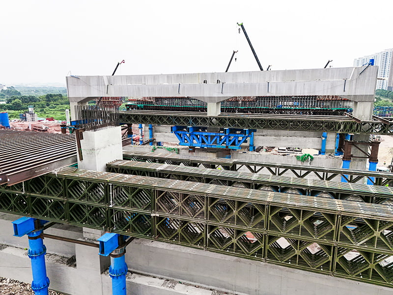
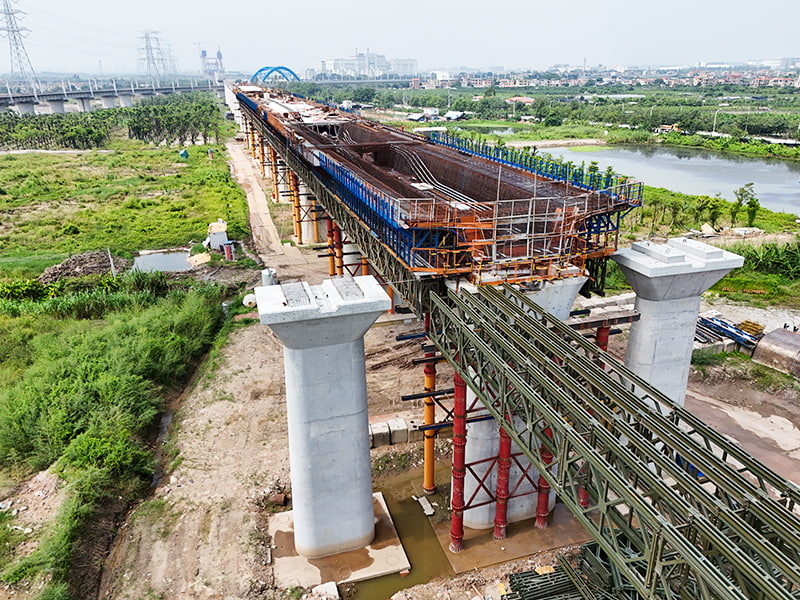
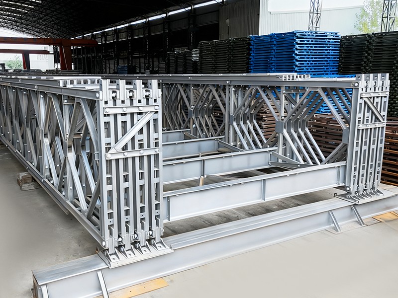
The Large-Span Heavy-Load Railway Super Bailey Construction Support is designed for precisely this type of demanding application. Developed for major railway engineering projects, the system uses advanced 4 m × 2 m super Bailey panels and a single-span arrangement that can reach a total length of up to 39 meters. With a maximum stated load capacity of up to 900 tons, it provides a high-capacity temporary support solution for projects where conventional modular systems may not provide sufficient span, rigidity, or load-bearing performance.
Unlike ordinary temporary supports assembled from unrelated steel members, this system is based on a coordinated modular design. The main panels, connecting components, bracing elements, bearing arrangements, and supporting steelwork function as an integrated structural system. This approach simplifies engineering evaluation, improves erection consistency, and enables the support structure to be adapted to different site conditions without sacrificing the basic advantages of standardized components.
The system is particularly suitable for railway bridges, tunnel construction, deep excavation works, large-span structural assembly, heavy equipment support, and other infrastructure projects requiring a robust temporary load path. Its combination of large modular panels, substantial load capacity, single-span capability, factory-controlled fabrication, and project-specific customization makes it a strong option for contractors, engineering consultants, infrastructure owners, and international construction partners.
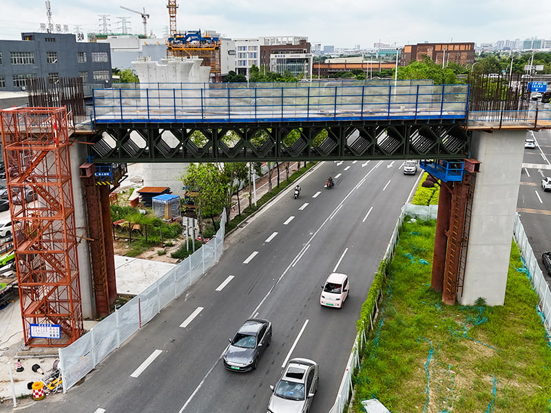
Large Span Heavy Load Railway Super Bailey Construction Support
Understanding the Need for Heavy-Load Railway Construction Support
Railway infrastructure projects are often constructed in locations where temporary support must function under difficult conditions. Construction may take place above existing roads, waterways, rail lines, urban areas, deep excavations, or environmentally sensitive zones. In many cases, the work area offers limited space for intermediate columns or ground-based support towers. A temporary structure must therefore bridge a considerable distance while carrying concentrated construction loads.
The temporary support system may be required to carry bridge segments, launching equipment, formwork, reinforcement cages, concrete placement systems, hydraulic jacks, lifting frames, and maintenance platforms. These loads are not always evenly distributed. A large lifting device may impose a concentrated reaction at one location, while construction materials can create changing load patterns as the work progresses. Wind, vibration, impact, temperature variation, settlement, and construction-stage movement also influence the design requirements.
Railway projects place particular emphasis on structural control because railway alignments and clearances are carefully defined. Excessive deflection can affect the accuracy of bridge assembly, concrete placement, track geometry, or the installation of permanent structural components. Excessive vibration or local deformation can also create safety risks for workers and equipment. For this reason, a temporary support system must provide more than nominal strength. It must offer predictable structural behavior throughout the construction sequence.
Traditional solutions may rely on numerous temporary columns, welded site-built frames, heavy scaffolding towers, or individually fabricated support assemblies. These approaches can work in suitable locations, but they may require extensive foundations, large work areas, high levels of site welding, and considerable dismantling time. They can also be difficult to reuse and challenging to inspect when components are produced under variable field conditions.
A super Bailey construction support addresses these challenges through a modular steel arrangement engineered for large spans and heavy loads. Standardized panels can be combined into a configuration selected according to the required span, load case, support condition, and construction method. The resulting system offers a structured alternative to improvised temporary works and provides an efficient route from design approval to site assembly.
Product Configuration and Structural Concept
The product is based on 4 m × 2 m super Bailey panels. These panels serve as the principal modular elements of the support system. Their dimensions provide a practical balance between structural capacity, transportation, handling, and erection efficiency. A panel can be connected with other panels to create a longitudinal support line, while additional layers or bracing arrangements can be introduced when the project requires higher resistance to bending, shear, buckling, or lateral instability.
The single-span arrangement is one of the product’s most important characteristics. The system can achieve a total span of up to 39 meters, subject to the project’s engineering design and site conditions. A single-span layout can reduce or eliminate the need for intermediate supports in the area below the structure. This is valuable when the ground is occupied by an existing road, operating railway, river channel, deep excavation, or active construction zone.
The structural system transfers loads from the supported construction operation through the modular panels and connected steel components to the end support locations. The design must account for vertical reactions, horizontal forces, local bearing effects, lateral stability, connection behavior, and construction-stage load changes. Depending on the application, the support may be combined with bearing beams, transverse distribution members, jacking equipment, temporary foundations, or other steel structures.
Because the system is modular, its configuration can be developed according to the project’s actual conditions. Engineers may select the number of panel layers, panel lines, transverse connections, bracing arrangements, deck or support beam layouts, and bearing details. The final configuration should be verified through project-specific structural calculations, including the governing load combinations and erection stages.
The stated maximum capacity of up to 900 tons places the product in a high-capacity temporary support category. This capacity is not a universal value for every configuration. Actual safe working performance depends on span, panel arrangement, support conditions, load distribution, connection details, lateral restraint, foundation behavior, environmental conditions, and the approved engineering design. Nevertheless, the available capacity demonstrates the system’s suitability for demanding railway and infrastructure applications.
Principal Product Parameters
| Item | General Product Information | Engineering Significance |
|---|---|---|
| Product type | Heavy-load railway super Bailey construction support | Designed for temporary support during major infrastructure construction |
| Panel size | 4 m × 2 m super Bailey panel | Provides a large modular structural unit for efficient assembly |
| Maximum stated span | Up to 39 m in a single-span arrangement | Can reduce the need for intermediate supports in restricted work zones |
| Maximum stated load capacity | Up to 900 tons | Suitable for heavy equipment, materials, structural assemblies, and construction systems when properly engineered |
| Primary application | Railway engineering and large-scale infrastructure construction | Supports bridge, tunnel, excavation, and related construction operations |
| Structural material | Engineered modular steel components | Combines high strength, repeatable fabrication, and potential reuse |
| Design approach | Single-span modular support system | Supports construction over obstacles or areas where columns are undesirable |
| Customization | Project-specific configuration and engineering | Allows adaptation to span, load, clearance, and site requirements |
The values in this table describe the product category and stated capability. A qualified engineer should confirm the allowable capacity and configuration for every project before fabrication, delivery, and erection.
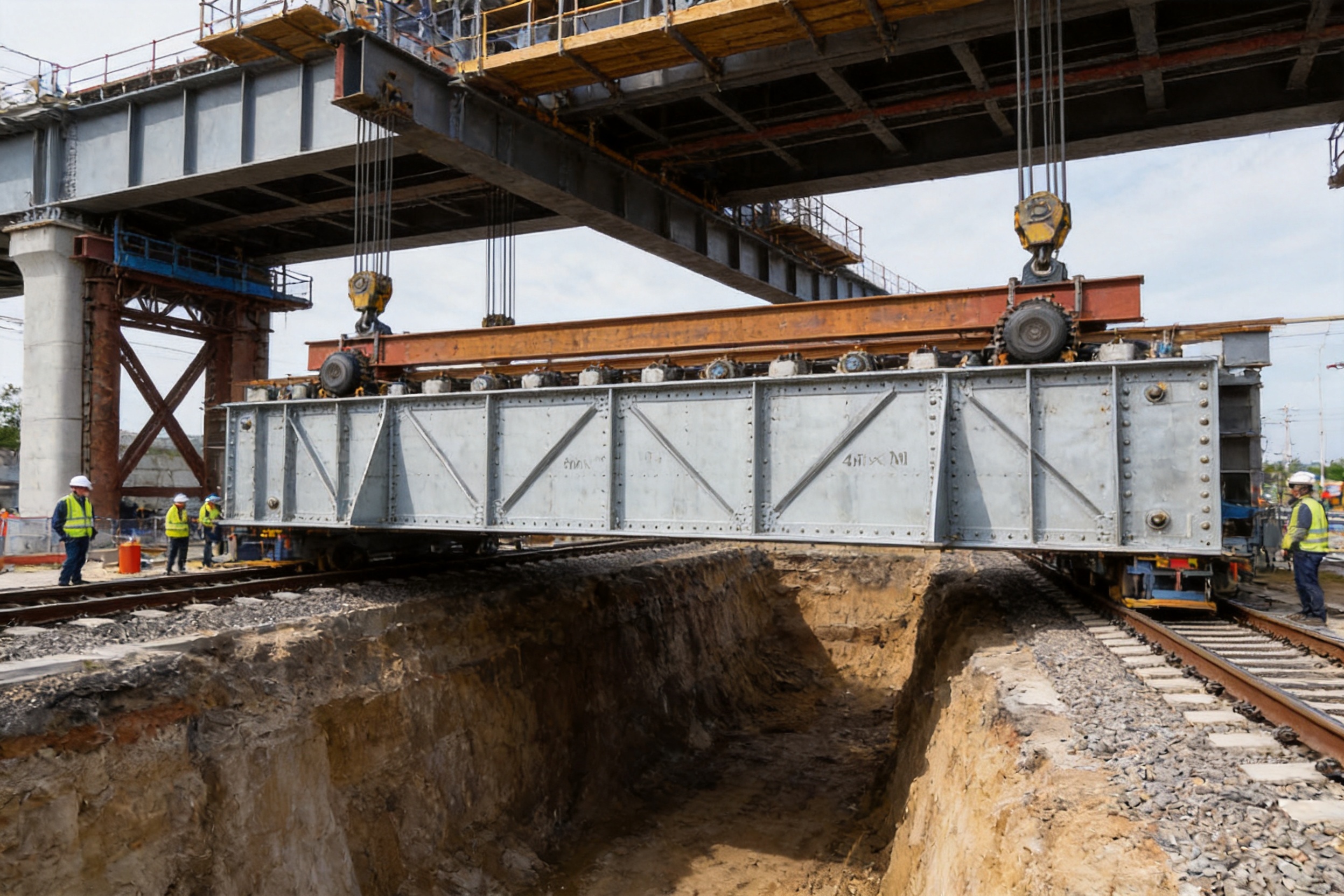
Advantages of the Large-Span Single-Span Design
The ability to span a substantial distance without intermediate support is a major advantage in complex construction environments. In railway work, the ground beneath a bridge may need to remain open for traffic, drainage, logistics, excavation, or the operation of other construction equipment. Installing temporary columns in such areas can create additional hazards and increase the need for foundations, protection systems, and coordination with other contractors.
A single-span support can simplify the construction zone by creating a clear space beneath the supported structure. This can improve material movement, reduce interference with earthworks, and provide better access for cranes, transport vehicles, pumps, and inspection teams. It can also reduce the risk of accidental contact between temporary columns and moving equipment or existing infrastructure.
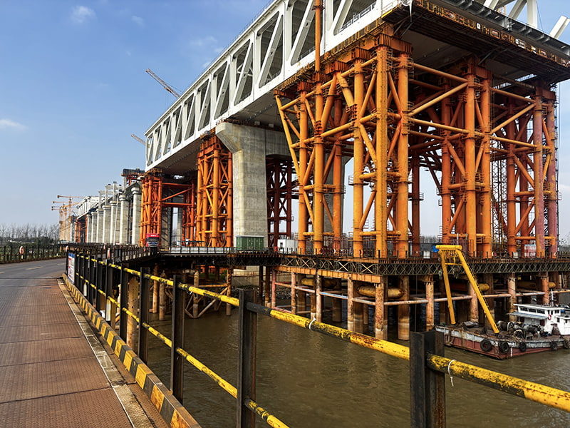
Large-span capability is particularly useful when the support must cross a waterway, roadway, railway corridor, or deep excavation. In these situations, the cost and complexity of intermediate foundations may be disproportionately high compared with the cost of the modular superstructure itself. A well-designed single-span system can provide a more direct load path and a more organized construction sequence.
The design also improves flexibility during project planning. Contractors can assess the support system as a temporary bridge-like structure rather than treating every support point as an isolated tower. This makes it easier to coordinate with lifting plans, temporary traffic arrangements, excavation schedules, and permanent structure installation.
At the same time, a long span requires careful attention to deflection, lateral restraint, connection behavior, and bearing conditions. The benefit of the system is therefore not simply that it is long. Its value lies in combining the large span with a modular structural arrangement that can be calculated, fabricated, inspected, transported, and erected in a controlled manner.
High Load Capacity for Demanding Construction Operations
Heavy railway construction can involve loads that exceed the practical range of ordinary temporary scaffolding and light modular support. Large precast beams, steel bridge sections, launching gantries, hydraulic lifting equipment, concrete delivery systems, and temporary working platforms may act together on the support structure. The support must resist not only the total vertical load but also local reactions and changing load positions.
With a maximum stated load capacity of up to 900 tons, the super Bailey construction support is intended for applications where significant structural mass must be temporarily carried. This capability can help contractors support heavy equipment during assembly, stabilize bridge components during installation, provide a temporary platform for construction operations, or carry formwork and materials during large-scale concrete works.
A high-capacity support structure can also improve construction planning. Instead of dividing a heavy operation into many smaller lifts or building a series of independent temporary frames, the contractor may be able to use a coordinated support arrangement capable of carrying the required construction stage load. This may reduce handling steps, shorten working time, and simplify the control of the construction sequence.
However, high capacity should always be understood in relation to the complete structural system. The modular panels may have substantial strength, but the supporting foundations, bearings, connection assemblies, transverse beams, and lateral bracing must also be designed for the same load effects. The load capacity of the system should therefore be established through a complete design package rather than by considering the panels alone.
Project-specific engineering should review dead loads, live construction loads, impact factors, wind, temperature, eccentricity, uneven loading, lifting conditions, accidental actions, and possible settlement. Where hydraulic jacking or staged lifting is involved, the sequence of load transfer should be analyzed carefully. The support system must remain stable during partial loading as well as at the final construction stage.
Comparison with Conventional Temporary Support Solutions
Conventional temporary support methods remain useful for many projects, but they may become inefficient when the required span and load are large. A tower-based support system, for example, may require several lines of columns and a substantial temporary foundation arrangement. In a congested railway corridor, each additional column can create a separate design, access, protection, inspection, and removal requirement.
Site-fabricated welded frames offer customization, but their quality can vary according to weather, access, worker skill, welding position, inspection facilities, and schedule pressure. Fabricating large frames entirely on site may also require extensive lifting equipment and temporary work areas. Once the project is complete, the frames may have limited reuse potential because they were designed for one particular geometry.
Standard scaffolding systems can be economical for light loads and short heights, but they may not be appropriate for very heavy concentrated loads or long unsupported spans. Their performance can be sensitive to base conditions, bracing quality, connector installation, and site modifications. A heavy modular Bailey support is engineered for a different class of temporary work, with larger structural members and a more deliberate load-bearing configuration.
Compared with these alternatives, the Large-Span Heavy-Load Railway Super Bailey Construction Support offers several competitive advantages:
First, it provides a combination of long-span capability and high load-bearing potential. Many temporary support systems can achieve one of these characteristics, but fewer can provide both within a modular configuration.
Second, standardized panels and accessories support repeatable assembly. Components can be produced, marked, inspected, packed, and delivered according to a defined bill of materials. This reduces dependence on ad hoc field fabrication.
Third, the system can be customized without losing its modular nature. Engineers can adapt panel arrangements, bracing, support beams, and bearing details to the project while continuing to use a family of compatible components.
Fourth, modular components may be dismantled and reused on future projects. Reusability can improve lifecycle value, especially for contractors involved in multiple bridge, railway, emergency response, or civil engineering works.
Fifth, a factory-manufactured system can offer more consistent quality control than temporary assemblies produced under difficult site conditions. Automated welding, standardized workflows, dimensional inspection, coating control, and documented quality procedures all contribute to better product consistency.
Competitive Performance Factors
| Evaluation factor | Super Bailey construction support | Potential limitation of conventional alternatives |
|---|---|---|
| Long-span construction | Single-span arrangement up to the stated project limit | May require multiple towers, columns, or special fabricated frames |
| Heavy load support | Maximum stated capacity up to 900 tons when properly configured | Light scaffolding may not be suitable for major concentrated loads |
| Site assembly | Modular components support organized erection | Site-built systems may require extensive welding and fitting |
| Adaptability | Panel combinations and customized supporting components | Rigid one-off frames may be difficult to modify |
| Reuse | Steel modules can be dismantled and redeployed subject to inspection | Permanent site-fabricated frames may have limited reuse value |
| Quality consistency | Factory production and controlled inspection processes | Field fabrication can be affected by weather, access, and schedule pressure |
| Restricted work areas | Large span can reduce the number of obstructions below the structure | Multiple supports may interfere with traffic, excavation, or logistics |
These comparisons are general. The most suitable temporary support solution depends on the project’s span, load, access, ground conditions, erection method, schedule, and applicable standards.
Advanced Manufacturing and Engineering Strengths
The performance of a modular steel support begins long before it reaches the construction site. Engineering design, material selection, fabrication accuracy, welding quality, dimensional control, surface treatment, and final inspection all affect the reliability of the finished system. Jiangsu Zhonghai Bridge Equipment Co., Ltd. combines design, engineering, precision manufacturing, quality management, and project support within an integrated production model.
This integrated approach allows the manufacturer to control the relationship between design intent and fabricated components. A project can be reviewed from the initial structural concept through to component production and site application. Potential conflicts involving panel dimensions, connection details, lifting points, transportation limits, and erection sequence can be identified earlier rather than discovered after delivery.
Engineering Design and Configuration Development
Each major construction support project should begin with a review of the site and the intended construction operation. Important information includes the required span, support elevations, clearance envelope, access routes, loading arrangement, equipment reactions, construction stages, bearing locations, foundation conditions, wind exposure, and installation method.
Using this information, the engineering team can develop a support arrangement that may include single or multiple panel lines, layered panels, transverse beams, lateral bracing, end supports, jacking points, and temporary foundations. The objective is to create a stable load path that can be verified for strength, serviceability, erection stability, and operational safety.
Computer-aided design and engineering documentation help ensure that the component schedule corresponds with the structural model. Drawings can identify panel positions, connection locations, bracing members, bearing interfaces, lifting points, and inspection requirements. Clear documentation is especially important when the system is shipped internationally or erected by a contractor who was not involved in the original design.
Material Preparation and Component Traceability
High-quality steel support systems depend on suitable raw materials and reliable traceability. Plate, section steel, fasteners, and other components should be procured according to the approved specification. Material certificates and inspection records provide evidence that the supplied materials meet the required chemical, mechanical, and dimensional criteria.
Material preparation may include cutting, drilling, edge treatment, forming, straightening, and part marking. Accurate preparation is essential because modular components must fit together consistently. Small dimensional errors can accumulate across a long support line, affecting connection alignment, bearing contact, or bracing installation.
Part identification also supports quality management and site efficiency. Marked components can be matched with fabrication drawings, packing lists, and erection instructions. This reduces the chance of mixing similar parts and helps the construction team identify the correct component during assembly.
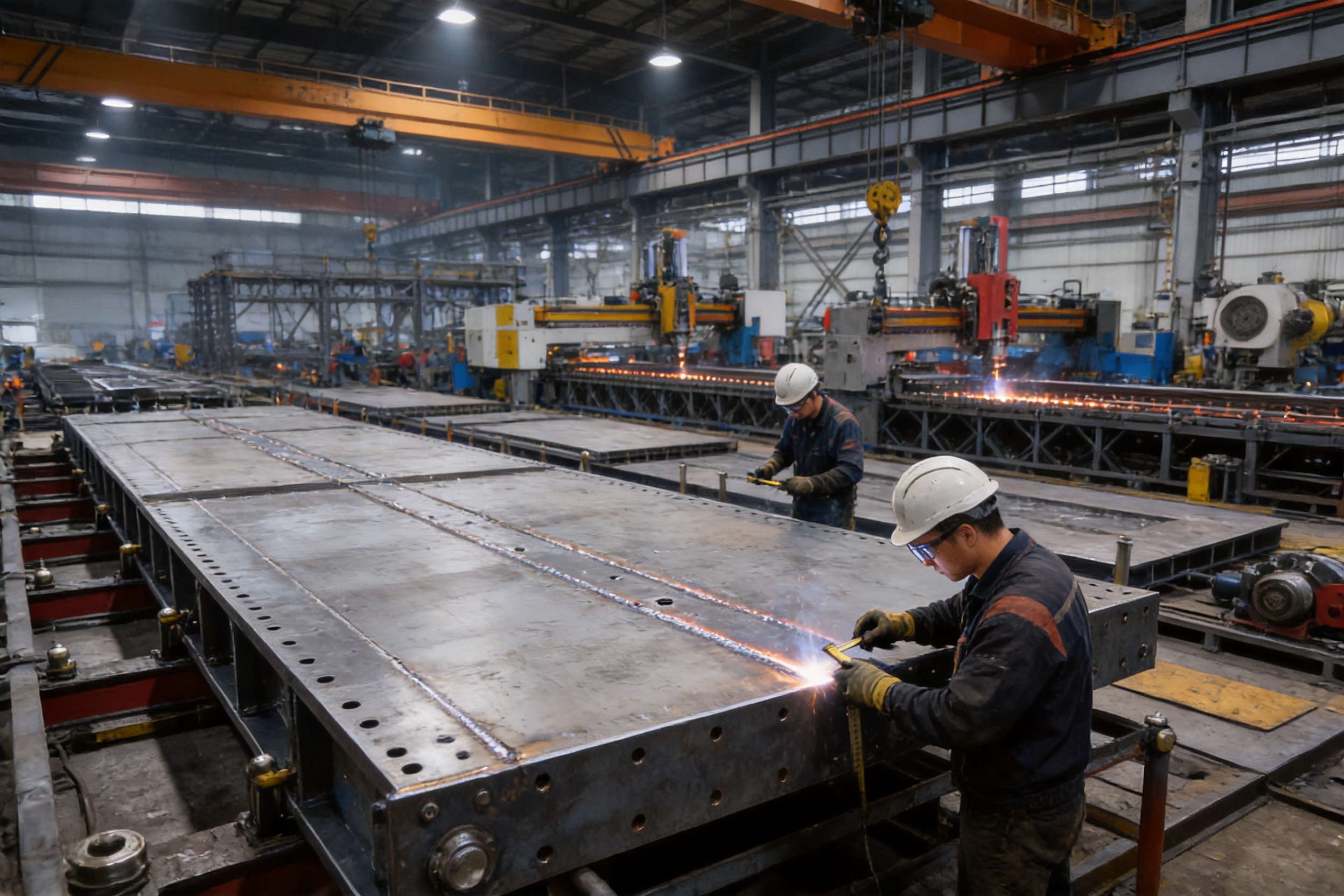
Automated and Controlled Welding
Welding is a critical manufacturing operation for steel bridge and support components. The manufacturer’s use of automated welding and standardized workflows can improve weld consistency, reduce variation between operators, and support repeatable production. Automated or semi-automated equipment can maintain controlled travel speed, heat input, and weld geometry within the approved procedure.
Controlled welding is particularly valuable for modular panels because the components are produced in series. Consistency across repeated panels ensures that connection holes, stiffeners, plates, and load-bearing details maintain their intended relationship. Welding procedures should be supported by qualified personnel, suitable consumables, preheating or interpass controls where required, and inspection methods appropriate to the component and governing standard.
After welding, components may undergo visual inspection and, where specified, nondestructive testing. Dimensional checks can verify that welding distortion remains within acceptable limits. Corrective work, if necessary, should be controlled and documented rather than performed informally.
Precision Fabrication and Dimensional Inspection
Modular bridge components are only effective when they assemble accurately in the field. Precision fabrication therefore plays an important role in the product’s competitive performance. Drilled holes, connection plates, panel frames, bearing surfaces, and bracing interfaces must be located according to the approved drawings.
Inspection may include measurement of overall dimensions, hole spacing, plate thickness, straightness, squareness, weld size, surface condition, and component identification. Trial assembly or fit-up checks can be used for selected components or representative modules. These checks help verify that the manufactured parts will connect properly before they are packed and transported.
Dimensional control also reduces site adjustment. Unplanned drilling, flame cutting, forced alignment, or unauthorized welding can weaken components and create uncertainty about the completed system. Factory accuracy allows the erection crew to focus on planned assembly rather than correcting avoidable manufacturing problems.
Surface Protection and Corrosion Resistance
Temporary construction supports are often exposed to rain, humidity, mud, concrete slurry, dust, industrial pollutants, and repeated handling. Surface protection is therefore important for maintaining service performance and preserving the components for future reuse.
Depending on the project requirements, steel components may receive surface preparation and a specified protective coating system. Coating selection should consider the expected exposure, storage duration, transport conditions, contact with concrete or soil, and whether the system will be reused in different environments. Areas damaged during handling or erection should be repaired using an approved procedure.
Good corrosion protection also supports inspection. A clean, well-prepared surface makes it easier to identify cracks, deformation, coating breakdown, corrosion pits, or other defects during routine checks. For reusable modular systems, maintenance records can be linked to component identification so that future deployment decisions are based on documented condition.
Quality Management and International Manufacturing Capability
Jiangsu Zhonghai Bridge Equipment Co., Ltd. is based in Zhenjiang, Jiangsu Province, an important industrial and transportation region in China. The company has developed manufacturing capabilities covering modular steel bridges, Bailey bridge systems, customized steel components, bridge erection equipment, construction support equipment, automated welding, and precision steel fabrication.
The company’s production model integrates engineering design, manufacturing, quality management, and delivery coordination. This is particularly useful for large temporary support projects because the product is not simply a collection of off-the-shelf components. It is an engineered system that may require customized dimensions, loading arrangements, support details, drawings, packing plans, and technical assistance.
Standardized workflows help maintain repeatability across production batches. Factory-scale manufacturing can provide better access to cutting machinery, welding stations, lifting equipment, inspection tools, coating facilities, storage areas, and trained production personnel than is normally available at a temporary construction site.
The company states that its products are produced to comply with ASTM, EN, and national specifications where required by the project. Applicable standards should be agreed during the engineering and procurement stage because the precise requirements may differ according to the destination country, contract documents, design responsibility, material grade, welding procedure, inspection level, and temporary works regulations.
International delivery performance is another important strength for global infrastructure contractors. Export projects require more than manufacturing. They require accurate packing lists, corrosion-conscious packaging, shipping coordination, document preparation, component labeling, and communication with overseas installation teams. A modular product is most effective when the delivered package allows the receiving team to identify and assemble the components efficiently.
The company has supplied products for infrastructure projects in China and abroad, including coastal engineering in the Maldives, temporary access bridges associated with the Shenzhen–Zhongshan Corridor, structural components for the Hangzhou Expo Center, multi-span Bailey bridge applications for the Lalin Railway, and emergency bridge deployments. These project categories demonstrate experience in transportation, coastal conditions, major public infrastructure, railway construction, and rapid-response applications.
Application in Railway Bridge Construction
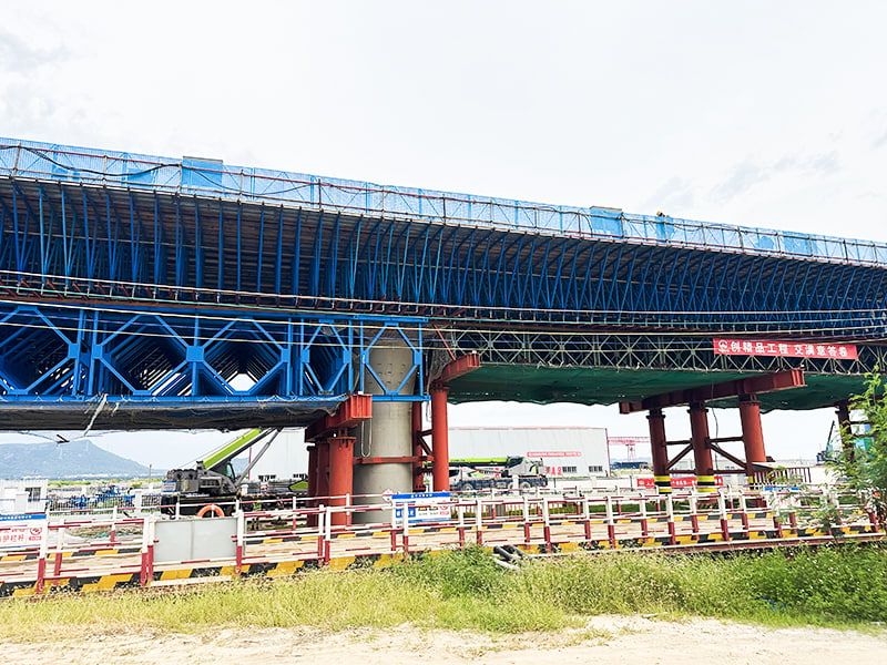
Railway bridge construction is one of the most suitable applications for a large-span heavy-load temporary support system. During erection, permanent bridge components may not yet form a complete self-supporting structure. Temporary support can carry segments, launching equipment, formwork, or assembly platforms until the permanent load path is closed.
The super Bailey support can be configured beneath bridge construction areas where a substantial clear span is required. It may support temporary crossbeams, lifting devices, erection platforms, or other elements used during the placement of bridge components. The support can also help maintain construction geometry while connections, concrete, reinforcement, bearings, or permanent bracing are installed.
Railway bridge projects often involve strict possession windows or limited access periods. A modular support can be assembled in advance, positioned according to the approved method statement, and removed after the critical operation is completed. This can support more efficient planning than a fully site-fabricated frame that requires lengthy preparation within the railway corridor.
Where an existing railway remains operational, the support arrangement must be designed to maintain required clearances and protect the operating line. The design must also consider vibration, accidental impact, construction traffic, emergency access, and the possibility of debris or tools falling into the protected area. A long-span arrangement may reduce the number of components placed close to the operating railway, although the final protection strategy remains project-specific.
Application in Tunnel and Underground Construction
Tunnel construction may require heavy temporary support at portals, cross passages, access shafts, excavation openings, or temporary roof structures. Construction equipment and materials can impose concentrated loads on temporary steelwork, especially where the permanent lining or final structural arrangement has not yet been completed.
A super Bailey construction support can be adapted to provide temporary load transfer across an excavation or opening. Its modular structure may help create a working platform or support a temporary roof arrangement while other construction activities continue below. The ability to provide a substantial span can be useful where columns would obstruct excavation, vehicle movement, ventilation, drainage, or emergency access.
Underground and semi-underground applications require particular attention to access, lifting, ventilation, water, corrosion, and inspection. Components should be delivered in sizes compatible with the available route, and the erection method should account for restricted headroom or limited crane access. The support must be checked for uneven bearing, possible water-softened ground, and construction loads that may not be centered on the system.
When used near a tunnel portal or deep excavation, temporary support may need to coordinate with retaining walls, ground anchors, struts, piles, or other temporary works. Clear interface drawings and a defined responsibility matrix are important so that the Bailey system and surrounding structures are not designed in isolation.
Application in Heavy Equipment and Material Support
The product can provide temporary support for heavy construction equipment and materials used in railway and civil engineering. Examples may include lifting gantries, launching systems, hydraulic jacks, precast segments, large steel assemblies, formwork systems, reinforcement cages, concrete equipment, and temporary work platforms.
The arrangement should be designed around the actual equipment reactions rather than only its total mass. Wheels, rails, outriggers, jacking points, or support feet can create concentrated forces. Moving equipment may introduce dynamic effects, braking forces, acceleration, or eccentric loading. The support deck and transverse distribution members must spread these forces appropriately to the modular panel lines.
A carefully planned support system can improve equipment utilization. Heavy equipment may be positioned on a stable temporary structure close to the work front, reducing the need for repeated relocation or ground improvement. This can be particularly useful where the natural ground is weak, uneven, waterlogged, or unavailable for conventional heavy lifting operations.
Before equipment is placed on the support, the contractor should verify the approved loading plan, equipment position, operating limits, access route, and communication procedure. The support should not be modified, overloaded, drilled, welded, or used outside the approved arrangement without engineering review.
Application in Emergency and Temporary Access Works
Modular Bailey systems have long been associated with rapid access and temporary connectivity. In addition to planned railway construction, a high-capacity modular support can be useful in emergency response, flood recovery, disaster relief, and urgent infrastructure restoration.
Floods, landslides, earthquakes, bridge failures, and other emergencies can damage roads, rail corridors, culverts, and crossings. A modular steel system can be transported to the affected area and assembled using a planned sequence. When the required span or load is substantial, a super Bailey arrangement may offer greater capacity than a light access bridge or ordinary temporary scaffold.
Emergency projects often face incomplete information, difficult access, unstable ground, weather exposure, and limited time. The modular nature of the system supports logistical planning because the component types and assembly principles are standardized. Nevertheless, emergency deployment still requires competent engineering judgment, site investigation, inspection, and control of public and worker safety.
For temporary access applications, the system may be adapted to carry construction vehicles, emergency equipment, materials, or specialized transport. The required configuration will vary according to traffic class, span, deck arrangement, approach geometry, lateral restraint, and environmental conditions.
Design and Erection Workflow
A successful project begins with a complete technical brief. The client or contractor should provide the design span, support elevations, required clearance, intended load, construction sequence, environmental conditions, access limitations, and expected service duration. If the system will be used above an operating railway, road, or waterway, the relevant authority requirements should also be identified.
The engineering team can then develop a preliminary arrangement. This stage may compare different panel configurations, support locations, deck layouts, bracing options, lifting methods, and foundation concepts. The preferred arrangement should balance structural performance with transportation, erection time, site access, and total project cost.
After the arrangement is selected, detailed design documents should be prepared. These may include general arrangement drawings, component drawings, connection details, load calculations, reaction tables, erection drawings, lifting plans, inspection checklists, and operation or maintenance instructions. The documentation should identify assumptions and limitations clearly.
Factory production follows the approved design. Raw materials are prepared, components are fabricated, welded, inspected, coated, marked, and packed. Quality records should be collected throughout this process. Depending on the contract, the client or an independent inspection agency may witness material checks, dimensional inspection, weld testing, coating inspection, and final release.
On site, the receiving team should verify the shipment against the packing list. Components should be stored on suitable supports and protected from standing water, mud, impact, and unauthorized modification. Before erection, the contractor should confirm the condition of support foundations, bearings, access routes, lifting equipment, temporary restraints, and exclusion zones.
Assembly should follow the approved erection sequence. Panels and connectors must be installed correctly, with all required pins, bolts, bracing members, transoms, sway restraints, and bearing components in place. The structure should not be loaded until the responsible engineer or competent supervisor confirms that the required configuration has been achieved.
During loading, the construction team should monitor settlement, deflection, connection condition, bearing contact, unusual noise, movement, and local deformation. If the system includes jacks, the load transfer should be controlled and recorded. Any unexpected behavior should result in a controlled stop and technical review.
After the supported construction operation is complete, dismantling should be performed in a planned sequence. Loads should be removed gradually, and components should be inspected for deformation, cracking, corrosion, hole elongation, damaged threads, coating loss, or other defects before being returned to storage or prepared for reuse.
Recommended Project Sequence
| Stage | Main activities | Typical control objective |
|---|---|---|
| 1. Site review | Confirm span, elevations, clearance, loads, access, ground, and environmental conditions | Establish a reliable design basis |
| 2. Preliminary engineering | Compare configurations, panel lines, bracing, bearings, and erection methods | Select an efficient and stable arrangement |
| 3. Detailed design | Prepare calculations, drawings, load reactions, and method statements | Define the approved temporary works system |
| 4. Factory manufacture | Cut, drill, weld, inspect, coat, mark, and pack components | Achieve repeatable quality and assembly accuracy |
| 5. Delivery and receiving | Check documents, quantities, condition, and storage arrangements | Prevent missing, damaged, or mixed components |
| 6. Site erection | Assemble panels, bracing, beams, bearings, and restraints | Build the structure according to approved drawings |
| 7. Preloading and use | Verify alignment, apply controlled load where required, and monitor behavior | Confirm readiness for construction operations |
| 8. Dismantling and reuse | Remove loads, dismantle safely, inspect, repair, and store | Preserve components and support future deployment |
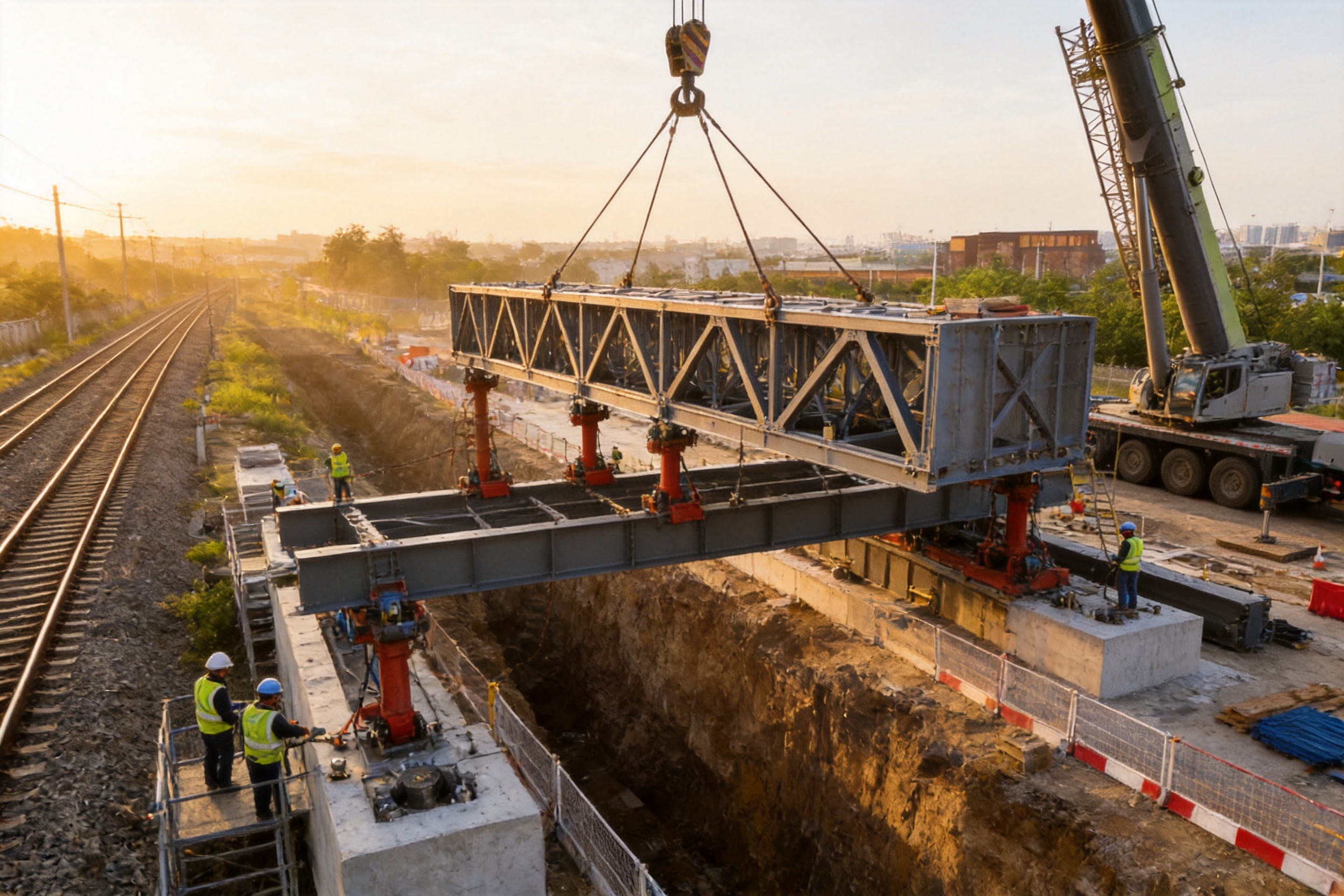
Safety, Inspection, and Operational Control
Temporary works require the same level of professional attention as permanent structures because failure can affect workers, equipment, public infrastructure, and the permanent project. A large-span heavy-load support should be managed through a formal temporary works process with defined design checks, approval responsibilities, inspection stages, and change-control procedures.
Before use, inspectors should verify the foundation or support points, bearing orientation, panel alignment, connection installation, bracing continuity, bolt tightening, pin security, deck or beam seating, access provisions, and protective measures. The inspection should be documented with checklists, photographs, measurements, and sign-off by the responsible personnel.
During operation, inspections should be repeated at intervals appropriate to the project risk. Additional inspections may be required after heavy rain, flooding, strong wind, impact, unusual vibration, equipment relocation, accidental overload, foundation settlement, or any modification to the construction sequence.
Warning signs can include unexpected deflection, local buckling, cracked welds, elongated holes, loose bolts, missing pins, bearing displacement, lateral movement, damaged bracing, foundation settlement, or corrosion that reduces section thickness. If any of these conditions are observed, the area should be controlled and the support should not continue in service until it has been evaluated.
Site personnel should understand the difference between the design load and an unrestricted permission to place any load on the structure. The approved capacity applies only to the specified configuration and load conditions. Materials should be placed within marked zones, equipment should remain within approved positions, and unauthorized storage or alteration should be prohibited.
Weather and environmental conditions should be included in the operating plan. Wind can create significant lateral force on formwork, temporary screens, lifting equipment, or partially completed structures. Rain can affect access and foundation conditions. Flooding can undermine temporary supports. Temperature changes can influence expansion, contraction, and bearing behavior. The project team should establish weather-related stop-work criteria in advance.
Logistics, Transportation, and Site Efficiency
Modular construction support offers logistical advantages because the system is divided into manageable components rather than shipped as one oversized fabricated frame. Panels, connectors, braces, beams, and accessories can be packed according to erection zones or assembly stages. This can simplify loading, unloading, inventory control, and transportation planning.
Component marking is especially important for overseas projects. Labels should correspond with the drawings and packing list so that the receiving team can identify each piece without relying on local assumptions. Packaging should protect connection surfaces, machined or drilled areas, coating systems, and small accessories during transport.
At the construction site, a modular system can often be preassembled on the ground before being lifted or pushed into position, depending on the approved method. Ground assembly may reduce work at height and improve access for connection checks. Alternatively, components may be installed sequentially where space is restricted. The selected method should consider crane capacity, lifting radius, temporary stability, nearby infrastructure, and available assembly space.
The large panel dimensions can reduce the number of individual structural units compared with systems made from many small members. Fewer primary units may contribute to faster assembly, although the actual time savings depend on the number of panel lines, connection type, site access, lifting equipment, and crew experience.
After completion, the support can be dismantled into transportable modules. This is beneficial for contractors that maintain a pool of reusable temporary works equipment. Components can be inspected, catalogued, and allocated to future projects, potentially reducing procurement time and lifecycle cost.
Customization for Different Project Requirements
Although the product is based on standardized super Bailey panels, project customization is an important part of its value. Railway and civil engineering sites rarely have identical geometry or loading conditions. A support system may need to fit between existing foundations, maintain a specified clearance, accommodate unusual bearing elevations, or support an equipment layout that differs from standard bridge loading.
Customization may involve the number and arrangement of panel lines, the use of double or multi-layer panel configurations, transverse distribution beams, lateral bracing, end frames, bearing plates, jacking points, access platforms, safety handrails, or special connection details. The manufacturer can also produce customized steel components that interface with the modular Bailey structure or with the permanent works.
For a deep excavation, the support may require specialized end conditions and coordination with retaining structures. For a river crossing, the arrangement may require protection against water flow, debris impact, or temporary scour. For a railway corridor, the design may need special clearance control, possession planning, and protective shielding. For heavy lifting, the support may require reaction plates or distribution beams beneath hydraulic equipment.
Customization should not mean uncontrolled modification. Every nonstandard component or change in panel arrangement should be reviewed through the engineering process. The final design should clearly identify which elements are standard, which are customized, and which installation tolerances or inspection requirements apply.
Economic and Lifecycle Benefits
The initial purchase price is only one factor when evaluating a temporary support system. Contractors should also consider design time, site fabrication, transportation, erection labor, equipment rental, foundation requirements, inspection, dismantling, storage, and future reuse. A modular system can provide value across several of these categories.
Factory production may reduce the amount of welding and cutting required on site. This can reduce hot-work permits, temporary power requirements, fire-watch obligations, and weather-related delays. Controlled manufacturing can also reduce rework caused by poor fit-up or inconsistent dimensions.
A long-span arrangement can lower the number of intermediate support points. This may reduce temporary foundation construction, excavation interference, traffic management, and protection measures. Where intermediate supports would be difficult or expensive, the effect on the total project cost can be significant.
Reuse creates another potential benefit. After inspection and any required repair, modular components can be redeployed for bridge construction, temporary access, emergency response, or industrial support. A reusable asset can provide value over multiple projects rather than being treated as a single-use temporary frame.
Reliable documentation also contributes to lifecycle efficiency. When component records, inspection results, repair history, and configuration drawings are retained, future engineers can make better decisions about reuse. This supports asset management and helps contractors build a dependable inventory of temporary works equipment.
Why Choose a Specialized Manufacturer
A specialized bridge equipment manufacturer can provide more than steel fabrication capacity. The technical challenge of a heavy-load Bailey construction support lies in coordinating structural engineering, modular compatibility, fabrication quality, transport, and erection. A supplier familiar with bridge systems is more likely to understand the interfaces between panels, bracing, bearings, deck systems, construction equipment, and site operations.
Jiangsu Zhonghai Bridge Equipment Co., Ltd. focuses on modular steel bridges, Bailey bridge systems, engineered structural components, bridge erection equipment, and precision steel fabrication. This product focus supports a deeper understanding of modular connection systems and the practical requirements of bridge and infrastructure contractors.
The company’s capabilities cover design, manufacturing, quality management, and technical support. This integrated service model can reduce coordination gaps between separate design offices, fabricators, and equipment suppliers. For international clients, a single technical partner can also simplify communication regarding drawings, manufacturing schedules, inspection documents, packing, and delivery.
The manufacturer serves transportation, water conservancy, military logistics, disaster relief, and international development projects. These sectors require products that can perform in different climates, logistics environments, and construction conditions. Experience across multiple application types supports the development of adaptable solutions rather than a narrow one-project approach.
Clients can contact the company for project evaluation, configuration recommendations, technical documentation, manufacturing coordination, and quotation preparation. Early contact is beneficial because a large-span heavy-load support should be integrated into the construction method from the beginning rather than added after the main lifting or bridge erection plan has already been finalized.
Procurement Considerations for International Buyers
International buyers should define the technical requirements before requesting a quotation. The supplier should receive the target span, design load, support elevations, expected service period, site location, applicable standards, environmental conditions, erection method, and delivery requirements. Equipment reactions should be supplied where heavy machinery will be placed on the support.
The procurement package should identify whether the buyer requires design calculations, stamped drawings, shop drawings, material certificates, welding documentation, nondestructive testing reports, coating records, inspection plans, erection instructions, or on-site technical support. These requirements can affect the manufacturing schedule and commercial scope.
Buyers should also clarify the division of responsibility. The manufacturer may design and supply the modular support, while the local engineer may be responsible for foundations, site conditions, temporary traffic management, erection supervision, or approval by local authorities. A written responsibility matrix helps prevent gaps in the design and construction process.
Shipping arrangements should consider component dimensions, container or breakbulk options, port access, customs documentation, unloading equipment, storage space, and local transport regulations. Small accessories such as pins, bolts, washers, bracing fittings, and protective items should be included in a controlled packing list to avoid delays during assembly.
Finally, the buyer should review the supplier’s quality procedures, manufacturing facilities, previous project experience, technical response time, warranty terms, spare component availability, and after-sales support. A strong supplier relationship is especially important for a complex temporary support system because site questions can arise during assembly even when the design is complete.
Frequently Asked Questions
What is a super Bailey construction support?
A super Bailey construction support is a modular steel temporary support system assembled from large Bailey-type panels, bracing, connectors, beams, bearings, and related steel components. It is designed to carry substantial construction loads across a defined span and can be configured for bridge, railway, tunnel, excavation, and other infrastructure applications.
What span can this railway support achieve?
The product is designed for a single-span arrangement with a total length of up to 39 meters. The allowable span for a specific project depends on the load, panel arrangement, support conditions, deflection limits, lateral stability, foundation behavior, and approved structural calculations.
What is the maximum load capacity?
The stated maximum load capacity is up to 900 tons. This is a project-dependent maximum and should not be treated as an unrestricted rating for every configuration. A qualified engineer must verify the capacity for the actual span, load distribution, equipment reactions, connection details, bearings, foundations, and construction sequence.
Why is a single-span arrangement useful in railway construction?
A single-span arrangement can reduce or eliminate intermediate supports below the work area. This is useful when the support must cross an operating railway, road, waterway, deep excavation, or congested construction zone. It can preserve clearance, improve access, and reduce interference with other construction activities.
Can the system support heavy lifting equipment?
Yes, the system can be engineered to support heavy lifting equipment, hydraulic jacks, launching systems, formwork, precast components, steel assemblies, and construction materials. The design must use the actual equipment reactions and positions, including concentrated, eccentric, moving, impact, and dynamic loads where applicable.
Is the support system reusable?
Modular steel components can generally be dismantled and considered for reuse after inspection. Reuse depends on the condition of panels, connectors, welds, holes, coatings, pins, bolts, and other components. Any damaged or deformed parts should be repaired, tested, or removed from service according to an approved procedure.
Can the product be customized?
Yes. The system can be adapted through panel arrangements, additional bracing, transverse distribution members, bearing details, customized steel components, jacking provisions, and other project-specific features. All modifications should be included in an approved engineering design and should not be made informally at the construction site.
What manufacturing processes support product quality?
The manufacturing process includes engineering review, material preparation, precision cutting and drilling, controlled or automated welding, dimensional inspection, surface protection, component marking, packing, and quality documentation. These processes help produce compatible modules with repeatable dimensions and consistent fabrication quality.
Which standards can be followed?
The manufacturer states that its products can comply with ASTM, EN, and national specifications as required by the project. The applicable standard, material grade, welding requirements, inspection level, and documentation should be established during the design and procurement stages.
Can the system be used for tunnel construction?
It can be applied to suitable tunnel and underground construction situations, including portals, excavations, access openings, temporary roofs, work platforms, and heavy equipment support. The design must consider limited access, headroom, water, ground conditions, ventilation, lifting methods, and coordination with surrounding temporary works.
What information is needed for a quotation?
Important information includes the required span, design load, equipment reactions, support elevations, clearance requirements, site location, environmental conditions, intended use, erection and dismantling method, delivery schedule, applicable standards, and required technical documents. Providing complete information helps the manufacturer develop a more accurate configuration and quotation.
Does the manufacturer provide international support?
The company serves international infrastructure and emergency response projects and can coordinate engineering, fabrication, quality documentation, packing, delivery, and technical communication. The specific scope of on-site assistance should be confirmed in the commercial and technical contract.
Conclusion
The Large-Span Heavy-Load Railway Super Bailey Construction Support is designed to address one of the most demanding areas of temporary infrastructure: carrying very heavy construction loads across a substantial span while maintaining a controlled and adaptable structural arrangement. Its 4 m × 2 m super Bailey panels, single-span capability up to 39 meters, and stated load capacity up to 900 tons make it suitable for major railway, bridge, tunnel, excavation, and heavy equipment support applications.
Its principal advantages over less specialized alternatives include long-span performance, reduced dependence on intermediate supports, modular assembly, potential reuse, factory-controlled fabrication, and project-specific customization. These benefits can improve construction access, reduce site fabrication, support safer work planning, and contribute to better lifecycle value.
The product’s effectiveness is reinforced by the manufacturing strengths of Jiangsu Zhonghai Bridge Equipment Co., Ltd. The company integrates engineering design, precision steel fabrication, automated welding, quality management, component inspection, surface protection, and international delivery coordination. Its focus on modular bridge systems and engineered structural components enables it to support clients from preliminary concept through production and project delivery.
For every application, the final support arrangement must be designed and verified according to the actual project conditions. Load capacity, deflection, foundation stability, bearing behavior, lateral restraint, erection sequence, environmental exposure, and inspection requirements all require professional review. When these factors are properly managed, the super Bailey construction support provides a strong, efficient, and dependable solution for large-span heavy-load railway construction.
References
1. AASHTO. Guide Specifications for LRFD Seismic Bridge Design and related temporary works considerations.
2. American Institute of Steel Construction. Specification for Structural Steel Buildings.
3. European Committee for Standardization. EN 1993, Eurocode 3: Design of Steel Structures.
4. European Committee for Standardization. EN 1090, Execution of Steel Structures and Aluminium Structures.
5. International Organization for Standardization. Quality management principles and quality requirements for manufactured steel components.
6. Railway construction temporary works guidance covering structural stability, construction-stage loading, inspection, and railway clearance management.
7. Manufacturer technical information for modular Bailey bridge systems, super Bailey panels, engineered bridge support equipment, and customized structural steel components.
Product: Large Span Heavy Load Railway Super Bailey Construction Support


We respond quickly to all international requests and provide technical support when needed.
Product Category
Bailey Bridge/Modular Bridge Modular Steel Bridge Pedestrian Bridge Modular Pipe Bridge Truss Bridge Steel StructureContact Us

+86-511-84522866
+86-13921582699

zhwm@zjql.com

Building 1,83#, dantu New Town, Yanjiang Road, Dantu District, Zhenjiang, Jiangsu, China
Copyright © Jiangsu Zhonghai Bridge Equipment Co., Ltd. All
Rights
Reserved
China bailey bridge for sale
bailey bridge supplier from china
